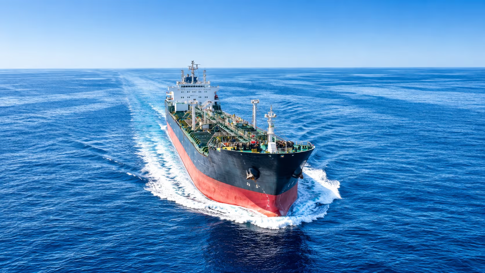
KNOW YOUR WEAR. PROTECT YOUR ENGINE.
Cylinder liner measurement
without opening the engine.
3D liner diameter measurement in situ - through the scavenge air slots, with the cylinder unit installed and the vessel alongside. Returned as a structured condition report for every cylinder.
LICENSED MARIDIS PARTNERMARLINER SYSTEMNO DISMANTLING
Liner Measurement
3D wear, ovality and wear rate for every cylinder - measured through the air slots in 10 to 30 minutes per unit, no dismantling.
Explore the service →Full Inspection
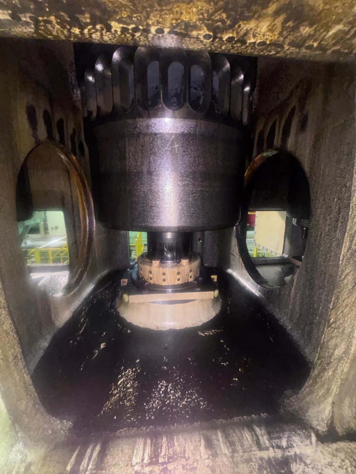
Piston crown, ring pack, groove clearance, lubrication and scavenge air space - documented in the same attendance.
Explore the add-on →- 500-980mm
- Liner bore
- 3,313
- Readings / revolution
- 10-30min
- Per cylinder
- Worldwide
- Attendance
Measure.
Approx. 12,000 points per liner, recorded in situ through the air slots. The cylinder unit stays installed.
Classify.
Wear, wear rate and ovality per cylinder, stated against applicable engine-maker criteria.
Decide.
One report as the basis for docking and budget planning. Indicative trend where sufficient data are available.
01 - THE GAP
Know the actual condition between overhauls.
Overhauls provide a snapshot at a single point in time. Between the intervals, wear, ovality and ring condition continue to develop - without any measured record. MLS closes that gap.
Between two overhauls Schematic, not to scale
- Overhaul - one snapshot in time
- Between intervals - no measured record
- MLS - measured in situ, unit installed
02 - WHAT WE DO
One attendance, five ways it pays off
Every service starts from the same measured surface. What changes is how far the evidence is carried - from a single liner profile through to a full condition report for the shore organisation.
All services →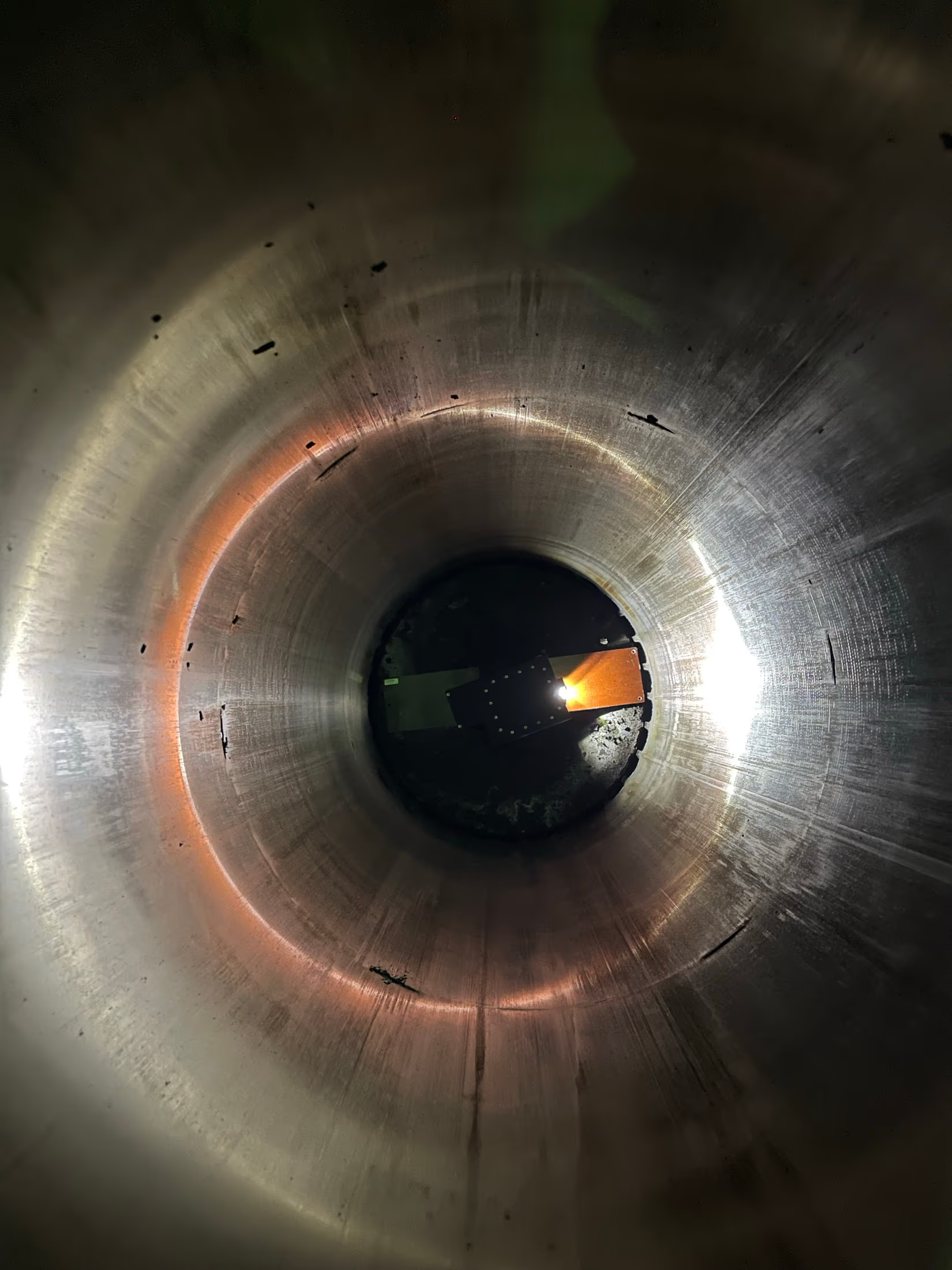

03 - ONE PORT CALL
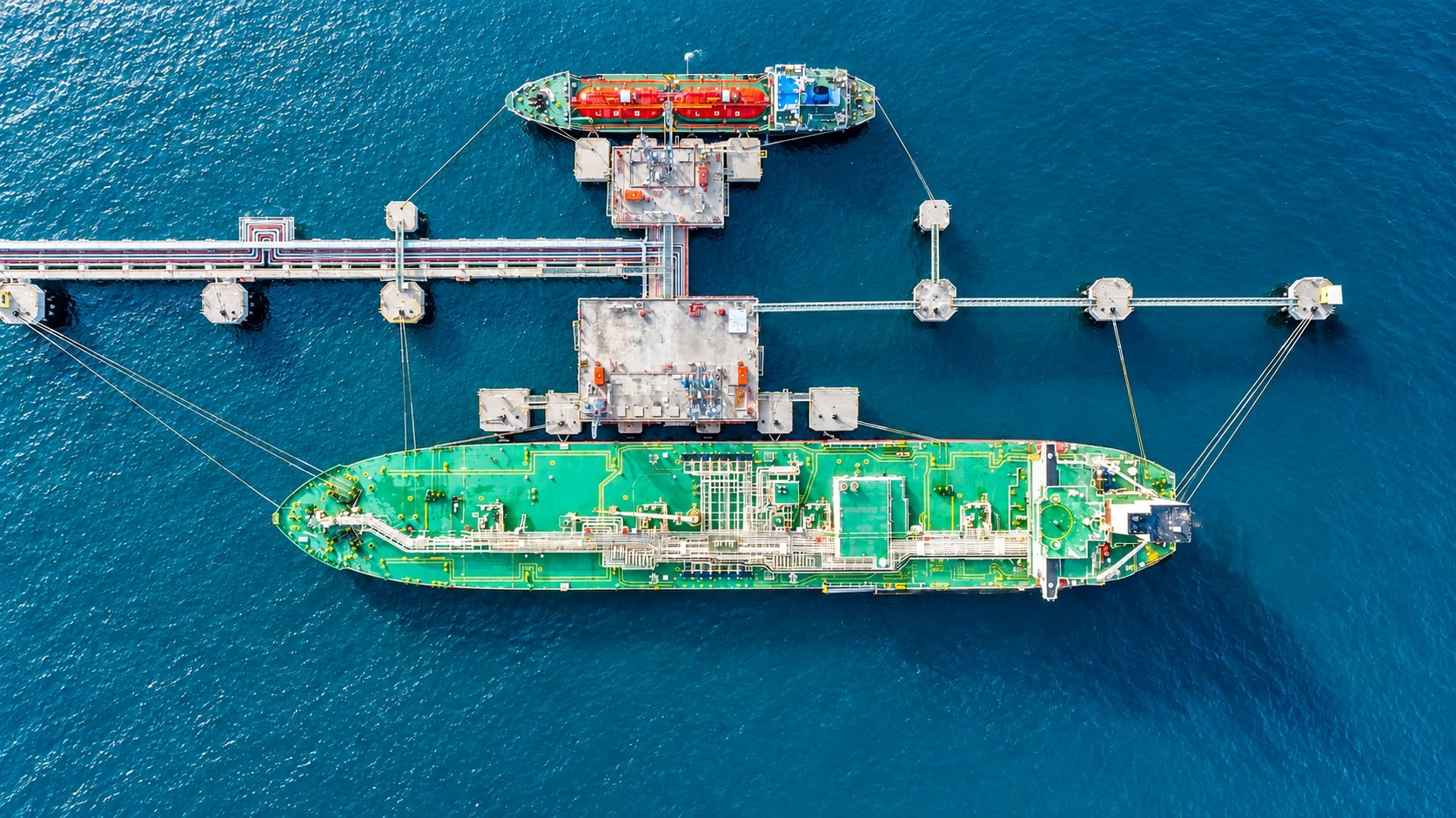
Everything happens alongside.
Pick a point on the berth to see what happens where - from the first check of your engine to the report that goes ashore. The vessel stays in port, the cylinder units stay installed.
01 / 05
01 · Compatibility
Is your engine a fit?
In-situ access through the scavenge air slots applies to two-stroke main engines with liner bores from 500 to 980 mm. Three inputs in the compatibility check give you the answer - no account required.
- Liner bore
- 500-980 mm
- Inputs to an answer
- 3
02 · Alongside
Measured at the berth, not in dock.
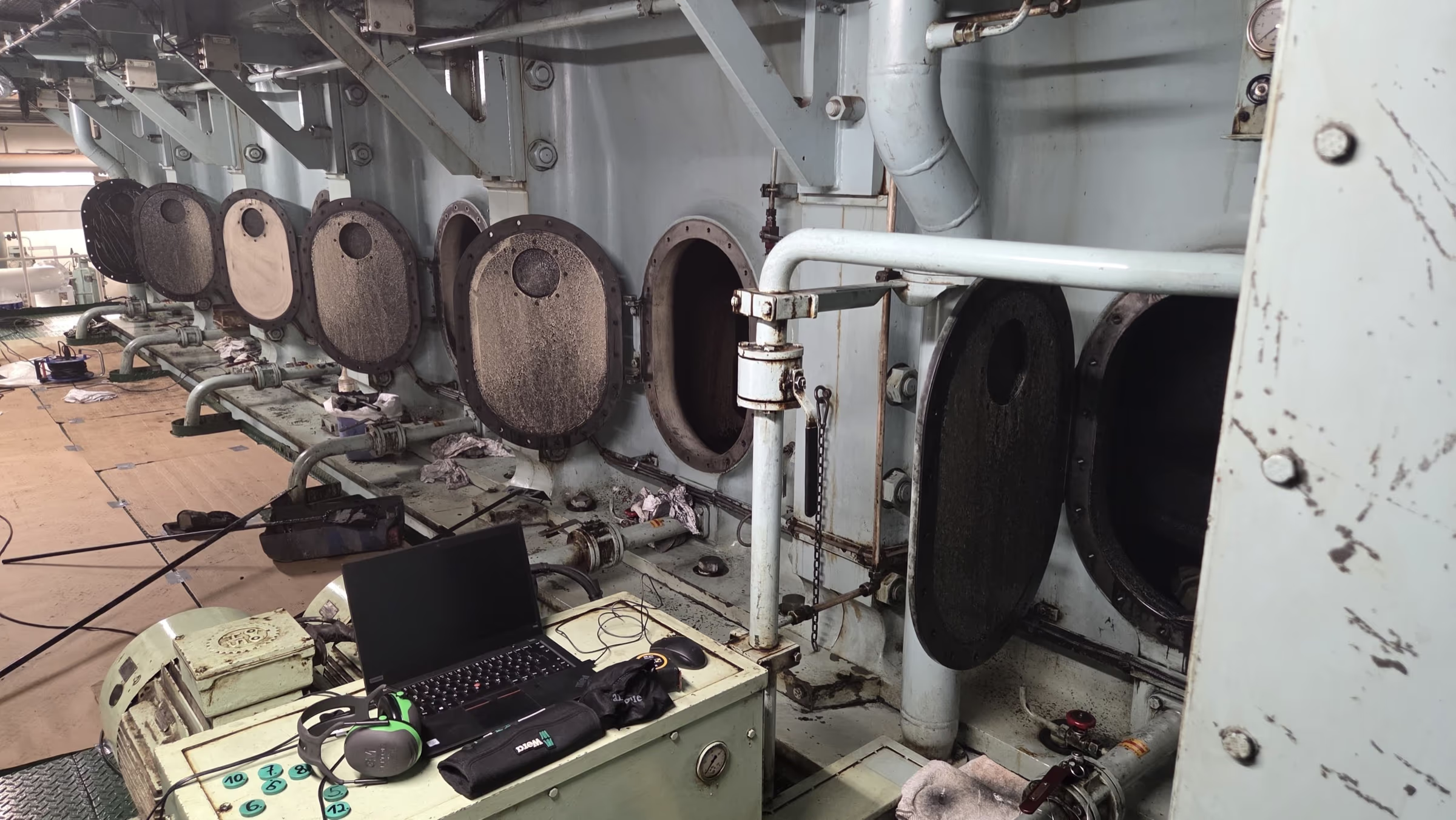
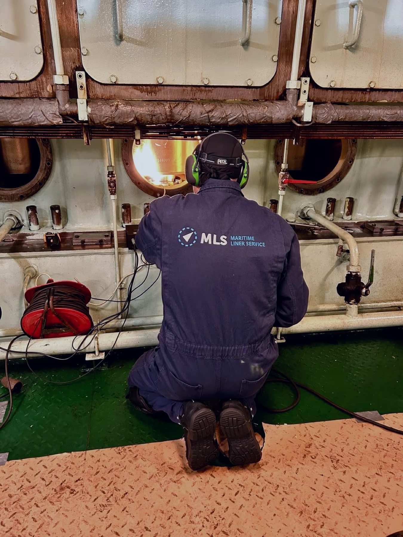
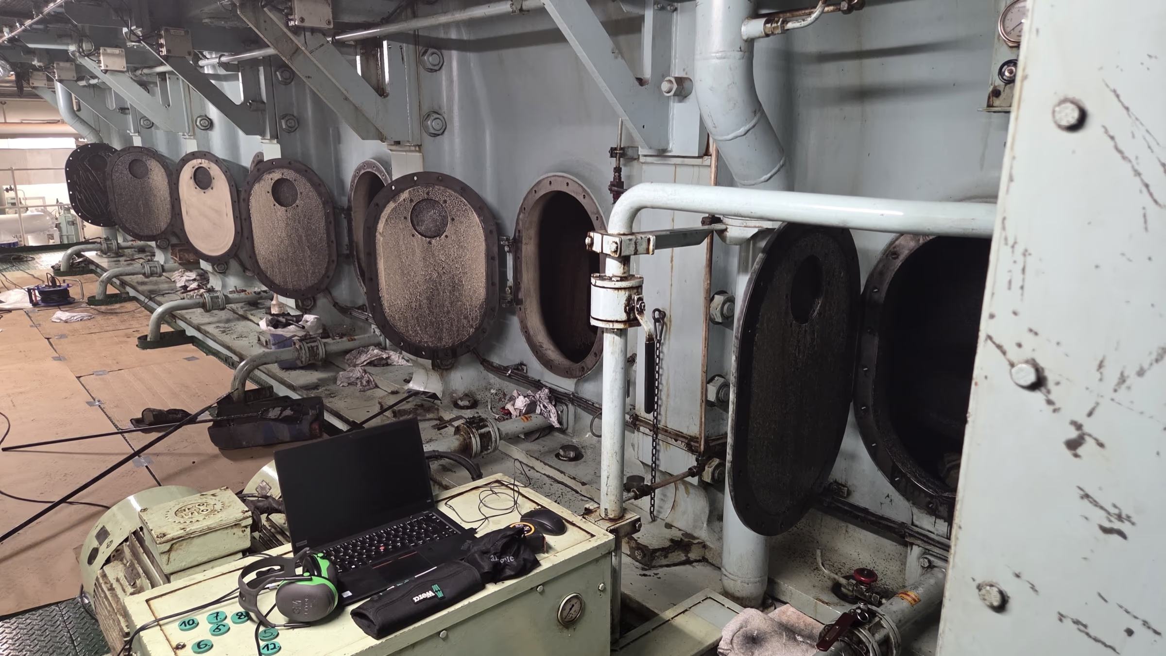
The attendance fits into a regular port call. The crew opens and cleans the access approx. two hours ahead - no docking, no dismantling of the cylinder unit.
- Per inspection
- 2-4 h
- Preparation ahead
- ≈2 h
03 · Liner measurement
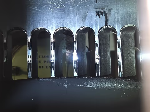
Through the scavenge air slots.
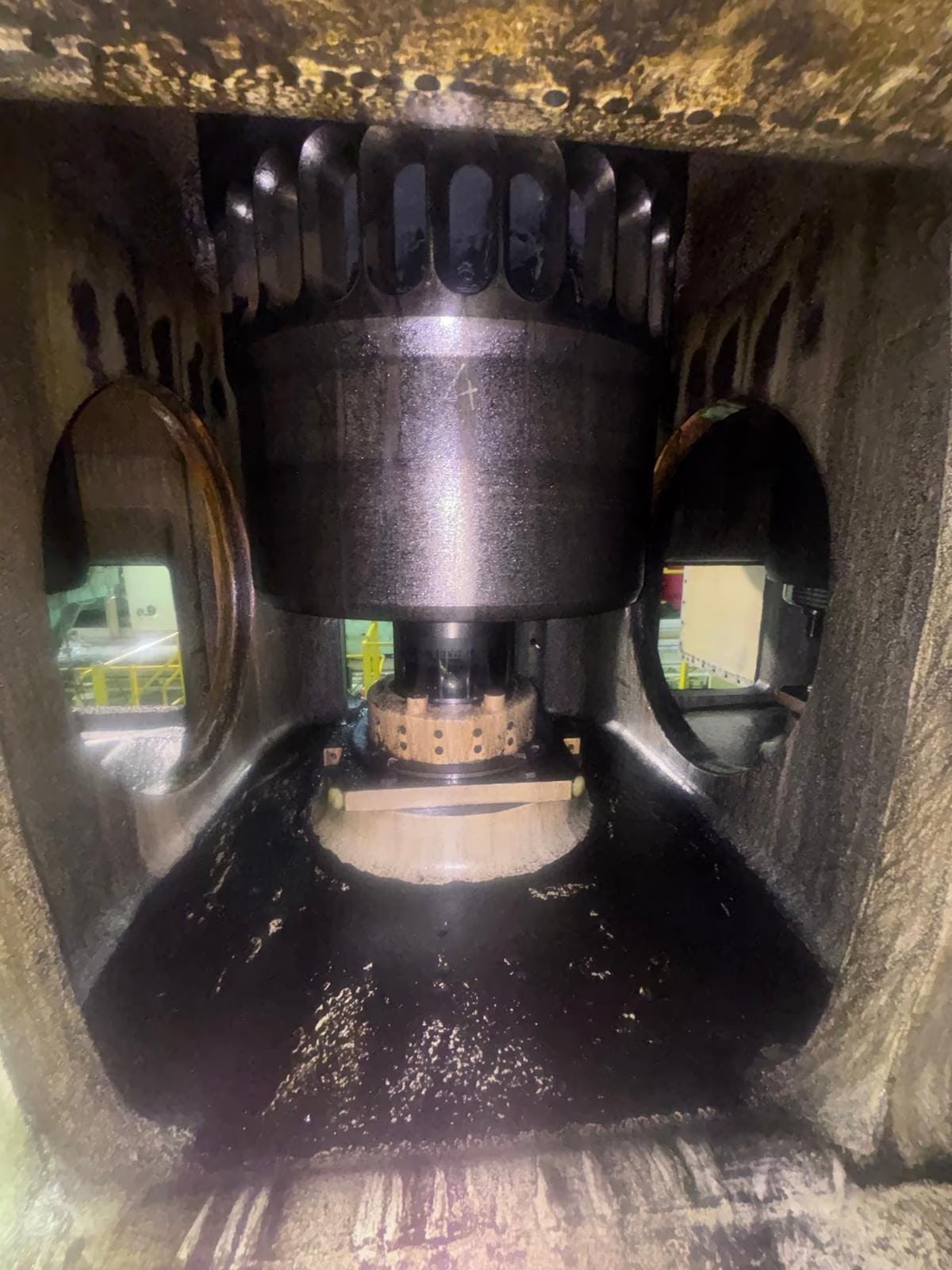
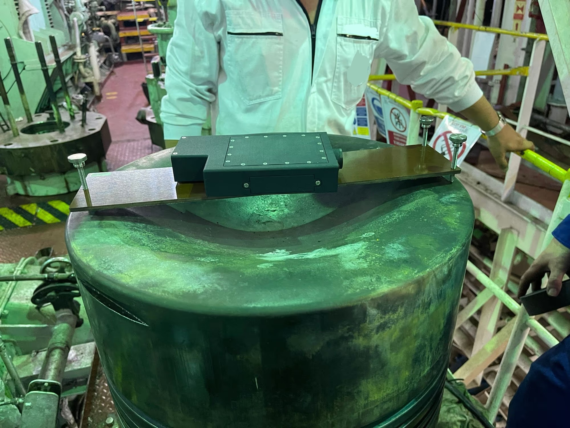
The MarLiner head goes in through the air slots and sits down on the piston crown. An automated run reads the liner wall level by level: 3D wear, ovality and wear rate for every cylinder.
- Per cylinder
- 10-30 min
- Points per liner
- 12,000
04 · Full Inspection
The rest of the unit, same attendance.
While the access is open anyway: piston crown, ring pack, groove clearance, lubrication and the scavenge air space, documented alongside the liner data.
- Whole engine, with the add-on
- 4-8 h
05 · Report ashore
One report for ship and shore.
A preliminary condition overview before departure, then the structured PDF: wear against the limit, wear rate, ovality and indicative remaining hours, cylinder by cylinder.
- Working days to the PDF
- 5
- Full circumference per level
- 360°
04 - Inside the measurement
Not an estimate. A measured surface.
The MarLiner laser head turns on the piston crown and reads the liner wall at 1,000 Hz - 3,313 readings per revolution, repeated level by level up the liner. What comes out is a full 3D surface, not eight caliper points.
Maximum measured wear - 9.5 % of the 4 mm limit for this bore.
Wear rate, derived from wear against logged liner running hours.
Maximum ovality - the figure a single-direction gauge cannot see.
Indicative remaining liner life at the measured rate.
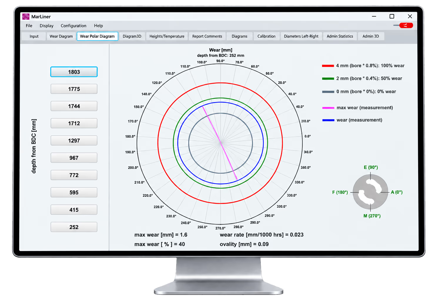

- Every level is temperature-compensated for the thermal expansion of both the liner and the device.
- The device logs its own eccentricity and tilt and rejects a run outside ±30 mm / ±2°.
- Diameters are recorded in two directions - fore-aft and exhaust-manoeuvre - so ovality is a measurement, not an assumption.
Figures from a reference measurement on a MAN B&W 6S50MC-C, 500 mm bore, 16,912 liner hours. Vessel identification removed. Remaining life is an indicative projection at the measured wear rate, not a guarantee.
05 - Condition report
Which liner needs attention, and when.
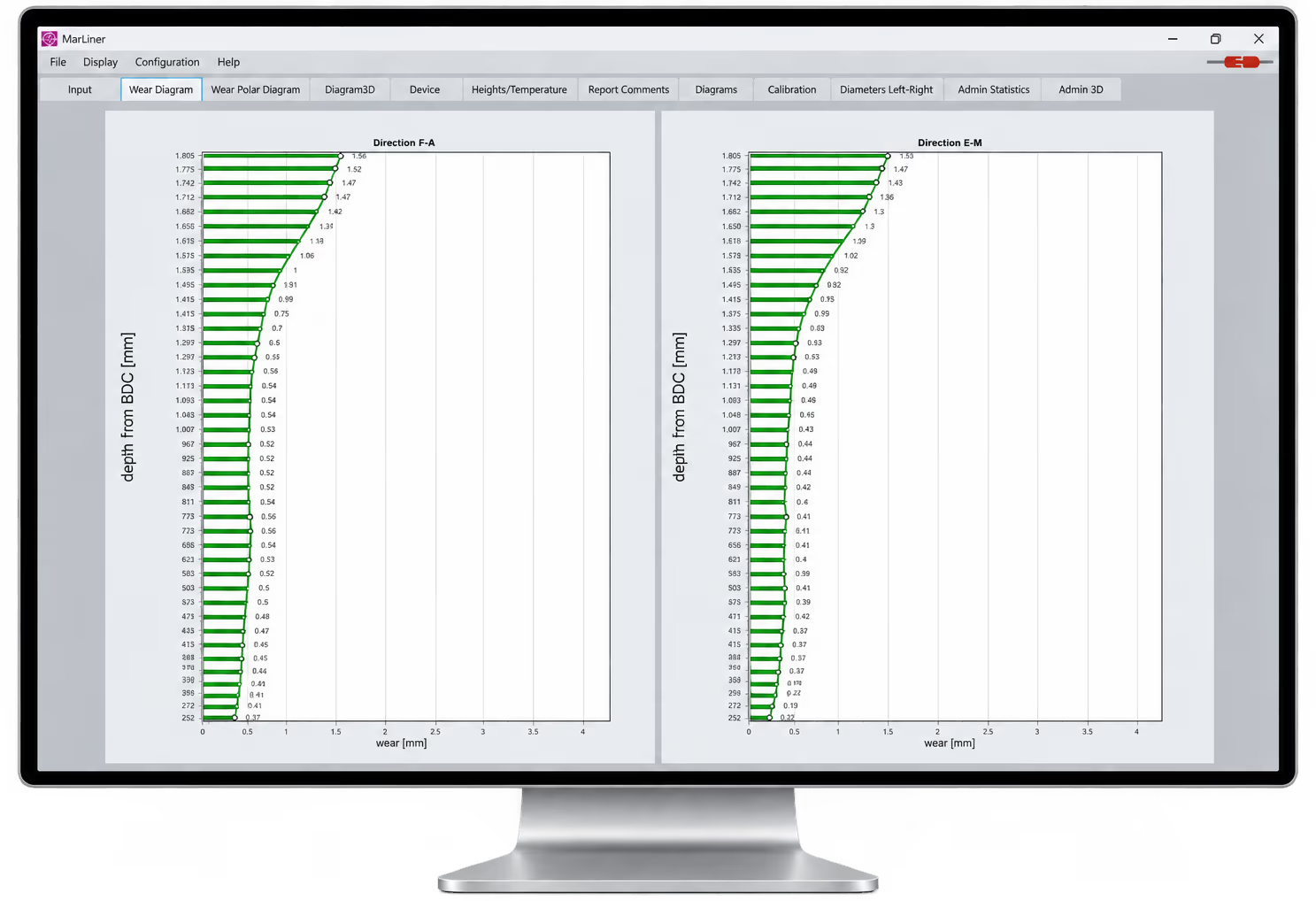
Every attendance ends in one structured report for ship and shore: wear against the limit for the bore, wear rate, ovality and the indicative remaining hours - worked out from wear over depth in both directions, the polar view and a 3D surface of every liner. Cylinder by cylinder, in the same layout every time.
- 360°Full circumference, read level by level up the liner
- 10Depth levels overlaid in one polar view
- 4Sides of the 3D surface, 90° apart
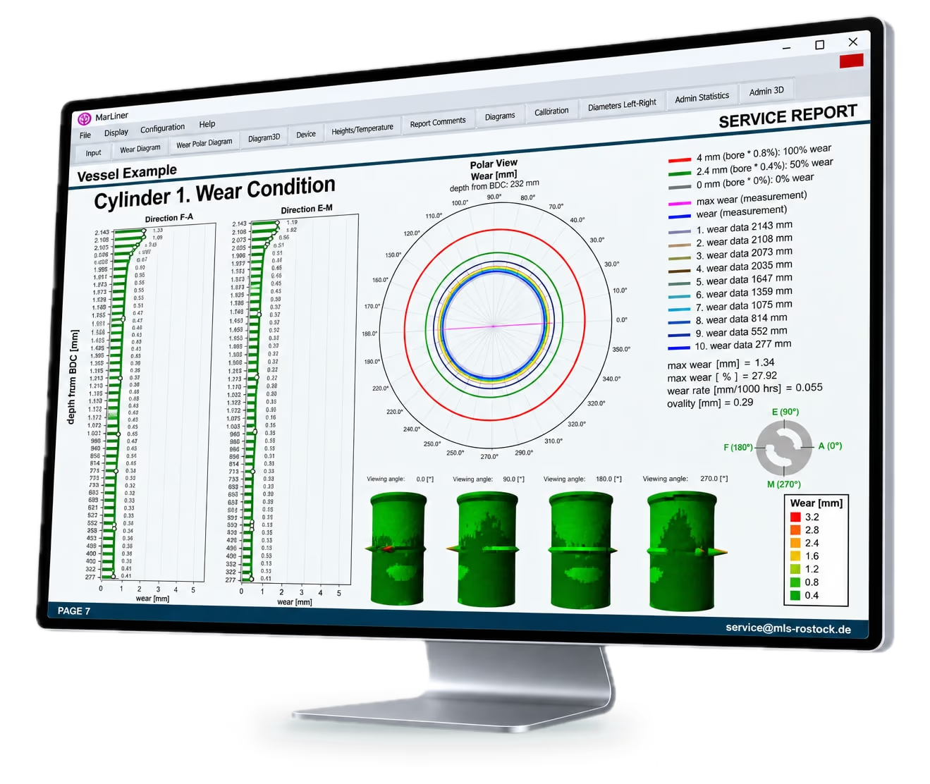
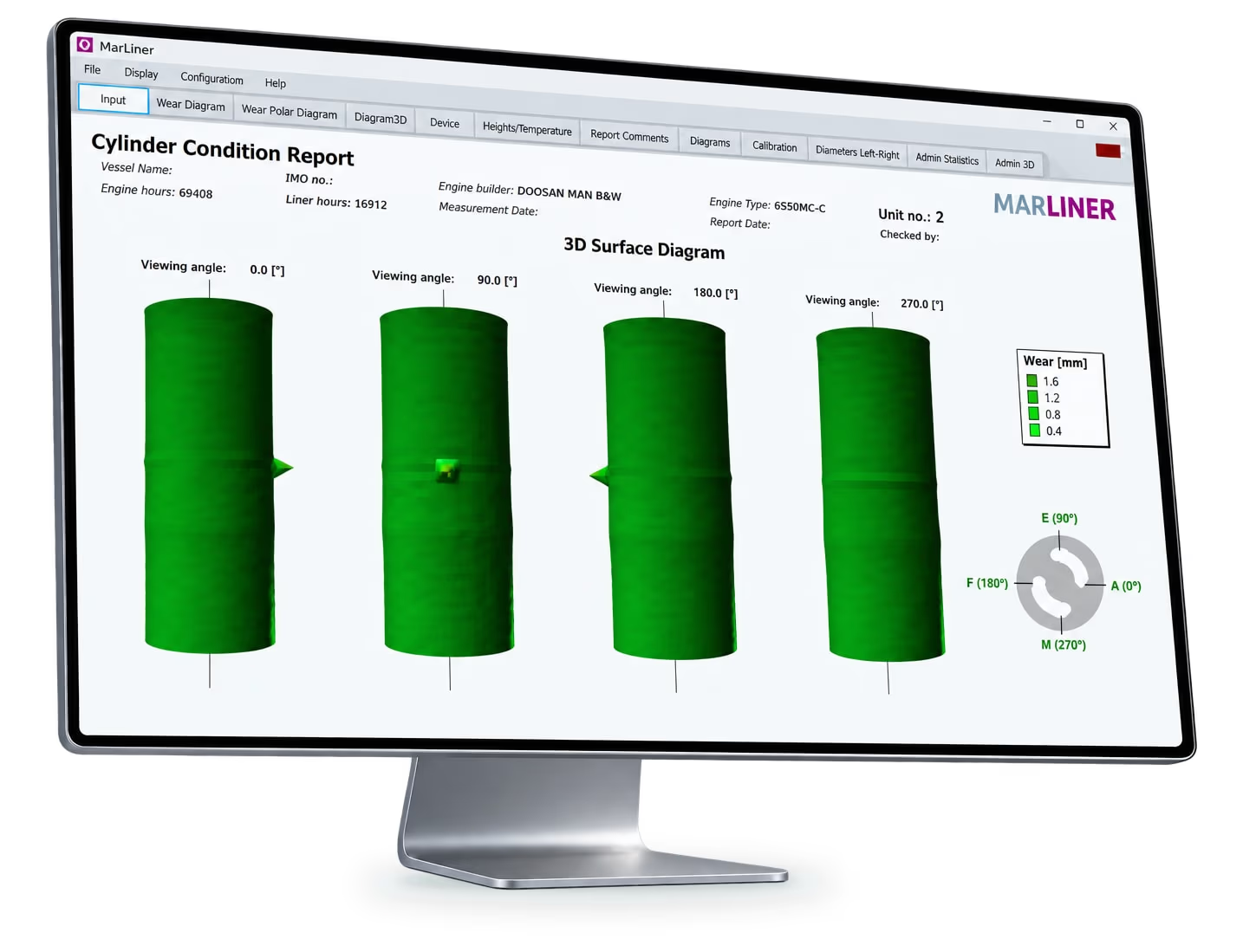
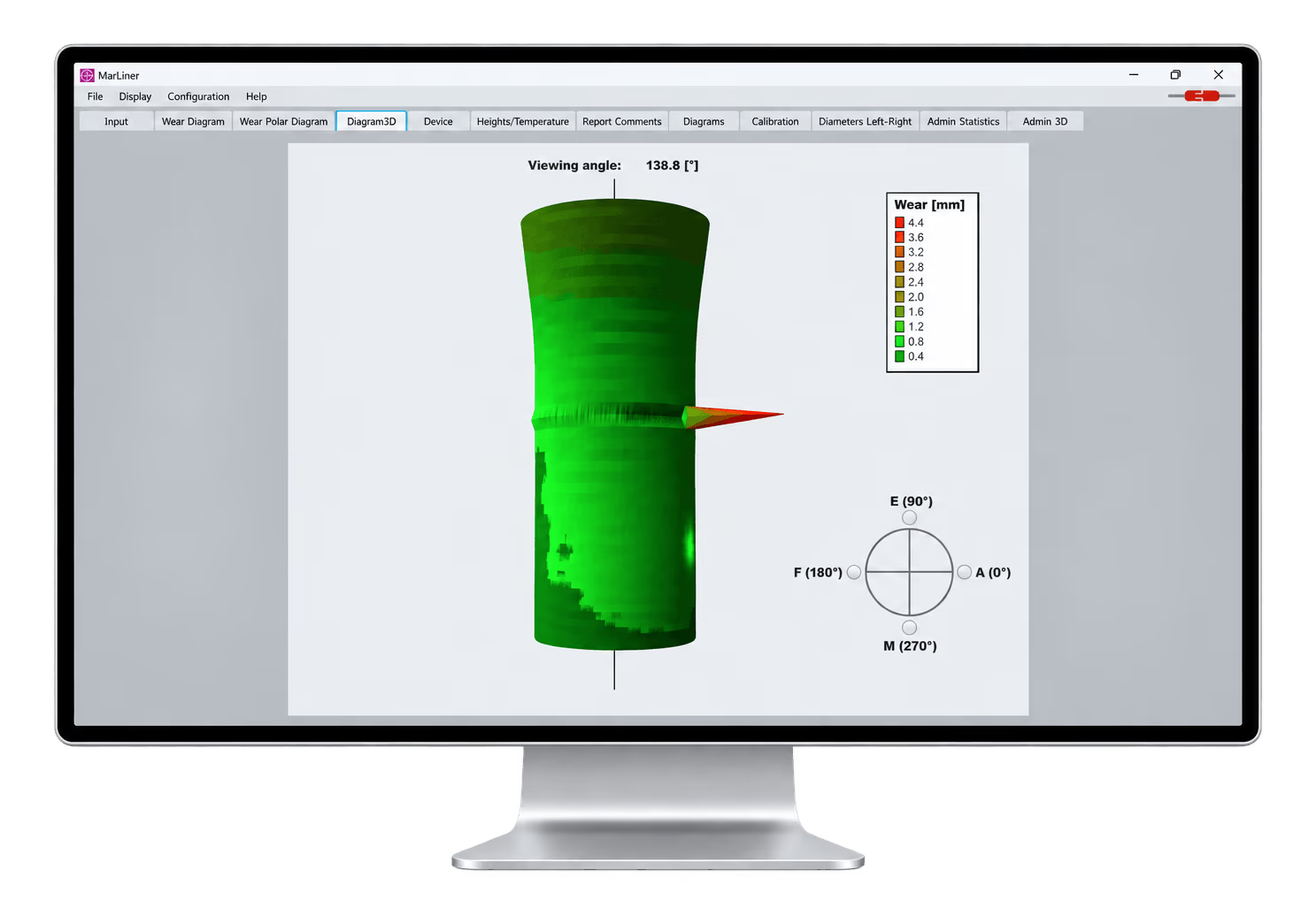
3D surface diagram
Four sides of the same liner.
The report turns every liner through 0°, 90°, 180° and 270°, colour-mapped by wear. Local wear at the lubrication points or around the ports shows up as a change of colour - where it sits, not only how deep it goes.
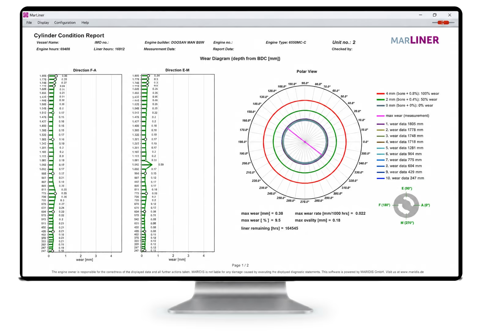
Cylinder condition report, page 1 of 2. The figures in section 04 come from this page: max wear 0.38 mm, wear rate 0.022 mm/1000 h, ovality 0.18 mm, 164,545 h remaining.
How to read the report →06 - Process
Seven steps, one attendance.
-
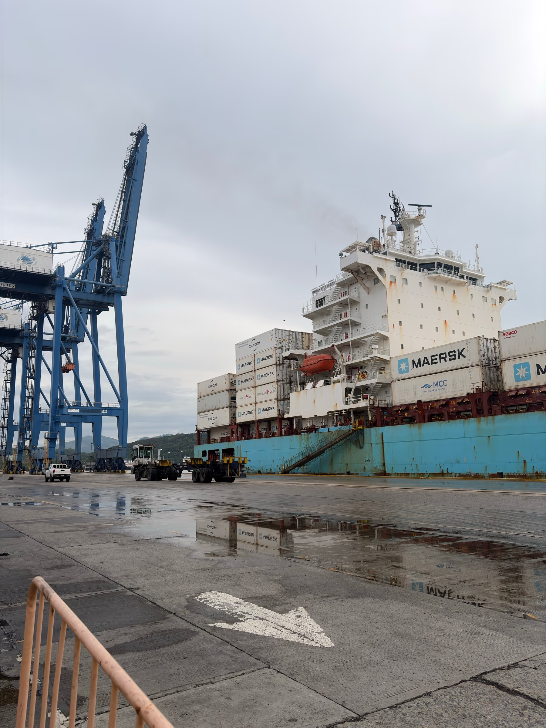 With the enquiry
Step 01 Configuration Check. Vessel, engine and configuration data are recorded. This is where the enquiry starts.
-
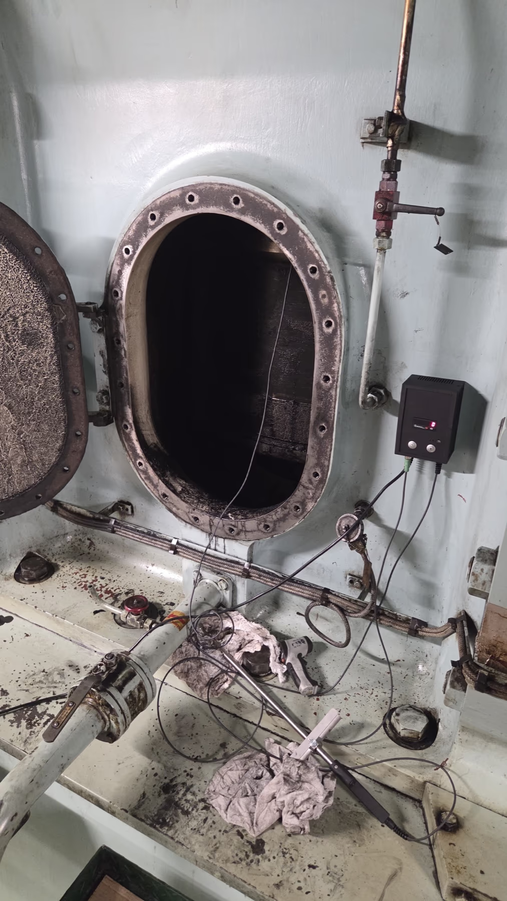 Approx. 2 h ahead
Step 02 Vessel Preparation. Access opened and cleaned, approx. two hours before the measurement.
-
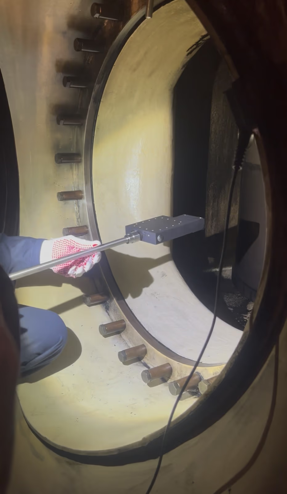 Through the air slots
Step 03 MarLiner Positioning. Inserted through the air slots and set down on the piston crown.
-
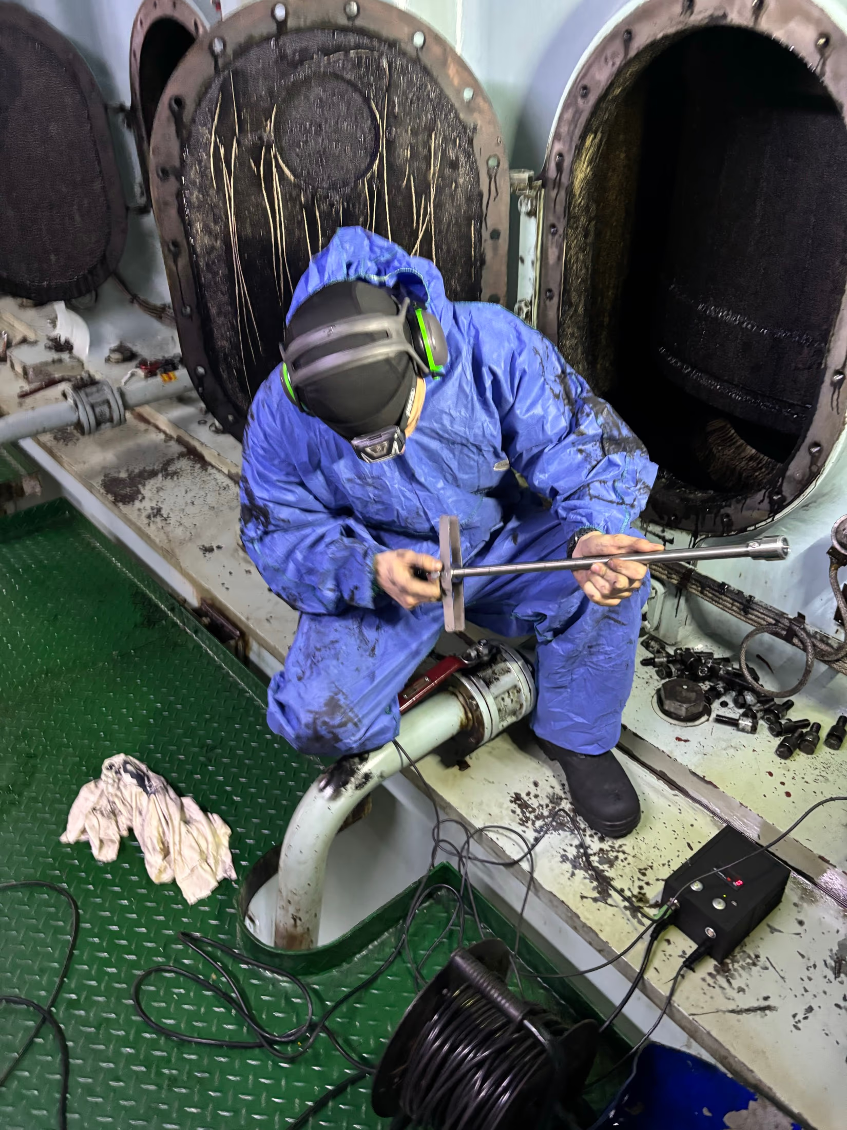 Core step · 10-30 min
Step 04 Liner Measurement. Automated run, 10 to 30 minutes per cylinder, approx. 12,000 points.
-
 Before departure
Step 05 Data Processing. Evaluation onboard, with a preliminary condition overview before departure.
-
 Optional add-on
Step 06 Full Inspection Add-On. Piston, ring pack, lubrication, deposits and scavenge air space.
-
 Within 5 working days
Step 07 Final Report. Structured PDF for the vessel and the shore organisation.
07 - BACKGROUND
Wear patterns, and where the method comes from
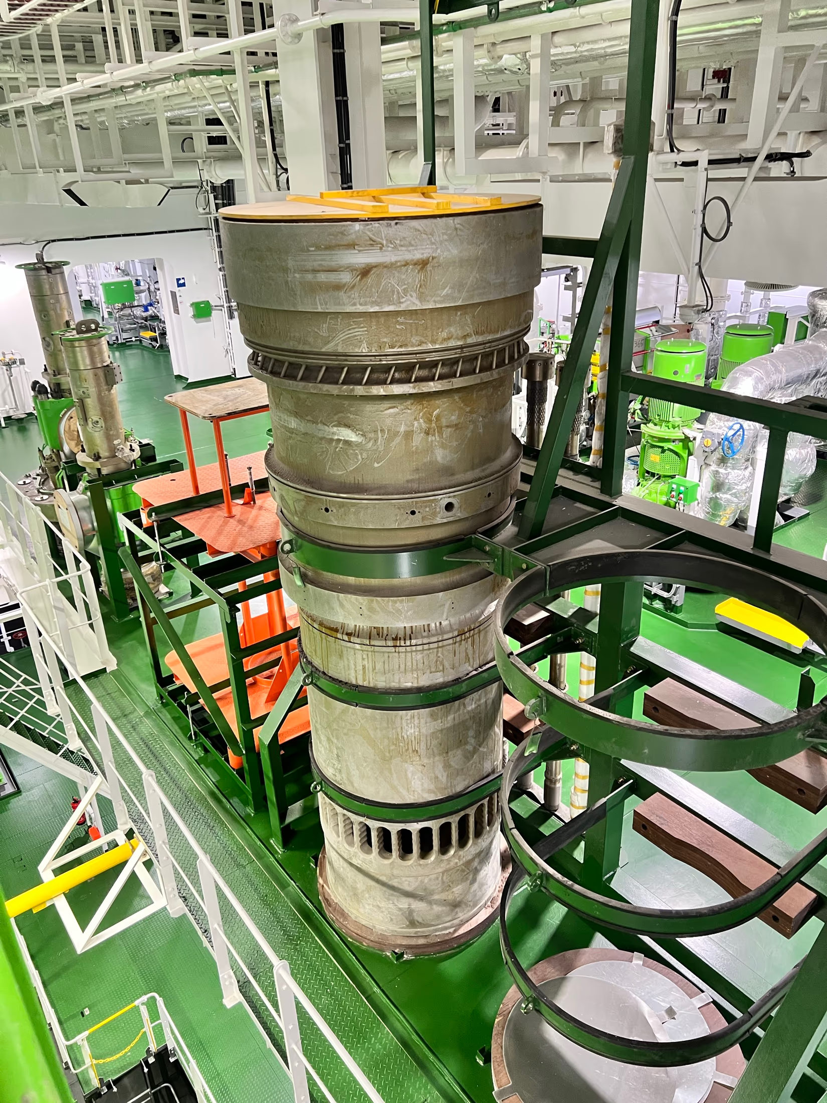
The measurement only means something against the damage it is meant to catch. These are the patterns we look for on the running surface - and the system the readings come from.
Knowledge base →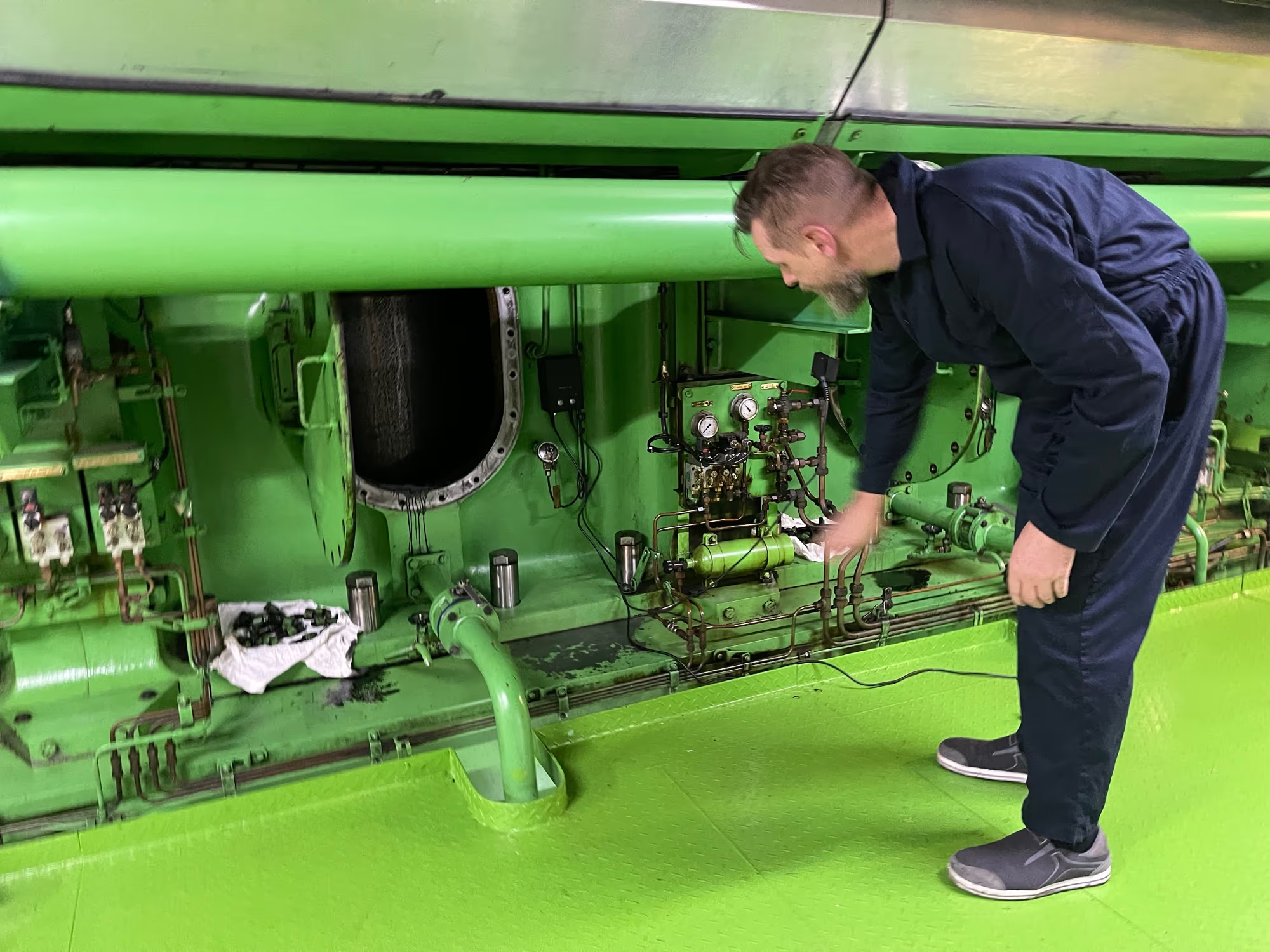
08 - COMPATIBILITY
Check your engine configuration
Liner bores from 500 to 980 mm on two-stroke engines. Three inputs tell you whether in-situ access through the air slots is applicable.

Tell us your port and ETA - we confirm attendance availability.
LEONARD GAU · MANAGING DIRECTOR
+49 381 000 0000 · INFO@MLS-SERVICE.DE
CONFIRMATION USUALLY WITHIN ONE WORKING DAY